
Born for success
„...Úgy lesz az emberiség bármi
kis népe is erős, nagy és halhatatlan,
ha az értelem szózatját követi...”
Széchenyi István
"...However small a people of the
human race, so will it become strong,
big, and immortal, if it will follow
the appeal of reason..."
© Katalin Tihanyi
14 june 2017
Az ifjú Tihanyi Kálmán a Pozsonyi Elektrotechnikai Szakiskolában komoly alapozásra tett szert a mérnöki tudományok terén, amint ezt naplója és korai találmányai tanúsítják. Tanulmányait befejezve és érettségijét abszolválva az első világháború második évében, 1915-ben, önkéntesként jelentkezett katonai szolgálatra. Ennek kapcsán a jelek szerint másfél évet meghaladó képzésben vett részt, minden valószínűség szerint a Ludovikán, mely előkészítette őt a katonai szolgálatra. Ennek befejeztével a Hadtörténeti Levéltár és Irattárban őrzött dokumentumok szerint 1917. január 1-jén tartalékos tisztjelölt lett a tüzérségnél, a 4. honvéd ágyúsezrednél.
Mint felderítő zászlós ő és hattagú csapata bevetésük után néhány hónappal a bronz vitézségi éremben részesültek az Ojtoz-völgyi csatában az ellenséggel szemben tanúsított „bátor magatartásukért”. Tihanyi maga ezt követően új területen, mint rádiómérnök folytathatta szolgálatát Polában, a Monarchia hadikikötőjének rádióállomásán. 1917. november 1-ei dátummal hadnagyi rangban részesült.
Egy feljegyzése szerint már a frontszolgálat során „a támadások közötti nagy csendben” is a televízióra gondolt. Kétségtelen, ez volt az a távoli cél, amely mindenek előtt foglalkoztatta.
A háború végén hazatérve – sokrétű feltalálói tevékenysége mellett – a televízió addig feltalált megoldásait feltérképezve, egyértelművé váltak számára a feladat kihívásai, és az a tény, hogy a valódi televízió egyedül a tudomány legújabb eredményeire alapozva lesz megvalósítható. Ezek megismerésére hét évet áldozott.
A korábbi megoldások szakszerű áttekintését és saját, akkorra már kiforrott terveit első ízben egy Az elektromos távolbavetítés címen megjelent cikkében, a Nemzeti Újság 1925. május 3. számának 23. oldalán ismertette a nagy nyilvánosság előtt.
Tihanyi terveivel megalapozta a modern televíziókészülék technológiáját. Miközben igyekezett tőkeerős támogatókat találni ügyének, tovább dolgozott a találmányain. Később számos további szabadalmat nyújtott be. Ezek között megtalálható az infravörös kamera, a plazmatévé és a falra akasztható síkképernyős televízió is.
Találmányai későbbi felhasználásával kapcsolatban kétségek is gyötörhették. Jól mutatja ezt a hagyatékában található 1939-ből való Húsvéti imája.
Tihanyi Kálmán: Húsvéti ima az erdőben
Te elképzelhetetlen Valami, nagy Hatalom
talán az Energia képében, ne engedd hogy
terjedjen az a tévhit hogy mi, az élőlények,
csak anyagból vagyunk. Pusztítsd ki a nagyképű
hülyéket kik azért mert a biológiai laboratóriu-
mokban kikutatták az élőlények központját az u.n.
Organizátort ezt arra magyarázzák, hogy csak
anyag van s nincs Lélek. Ennél megdöbbentőbb
borzalmasabb tudatot csak büntetésként küldhetnél
az Értelmeseknek de Te azt nem teszed mert
jó vagy. Jó oly értelemben ahogy azt mi soha
felfogni nem tudjuk.
Hiszen Te adtad a kis és nagy Organizá-
toroknak az életet melyet nem hagysz belőlük
elpusztítani addig míg ki nem élték magukat,
addig míg nem teljesítették kötelességüket.
Hiába pusztítják, irtják, morzsolják Őket, az Organi-
zátorokat, tovább „élnek” és a hozzájuk illő szervezetet fejlesztik,
növesztik, tökéletesítik. Elpusztítani nem engeded a
lelket belőlük míg a nekik rendelt életet
legalább is meg nem kezdték, legalább is
át nem terjesztik az emberi test, növény, bacilus, bogár
celláiba.
Mutasd meg tovább, könyörgöm, hogy a magban,
embryoban talált Organizátorban nem az anyag
hanem a Lélek a fontos.
Kell hogy ez a Lélek Tőled származzon!
Te, ezeknek az apró biológiai „Organizátor”-oknak a
nagy Organizátora engedd meg hogy mi a
Lélek kisugárzását az Észt ne arra használjuk
hogy Lelkeket öljünk ki milliószámra az anyagból.
Engedd meg, könyörgöm, hogy legalább a hozzánk
legrokonabb Anyagot, a másik embert kíméljük.
Pusztitsd el a politikusokat kik öldöklő
fegyvereket gyártanak, jaj milliószámra, s nem keresik,
csak ordítják, a Békét.
Ma jó voltam. Félretettem egy aranyszárnyú
bogarat a gyalogútról hogy el ne tapossák. Megcsókol-
tam egy fatörzset mert gyönyörű rügyet hozott
a világra.
De mi lesz holnap?
(Berlin, 1939. április)
Magyar Tudományos Akadémia Kézirattár, Letéti hagyaték
Az alábbiakban „A hét dokumentuma” sorozatunkban rendhagyó módon nem magyar, hanem idegen nyelvű cikket közlünk: Tihanyi Kálmán lányának, Tihanyi Katalinnak angol nyelvű cikkét, valamint a szabadalom főbb pontjainak fordítását. A szerzőnek ezúton is köszönetet mondunk az elküldött anyagért és a fordításért.
A találmány szabadalmi bejelentése – a magyar dokumentumok közül elsőként – 2001-ben bekerült a Memory of the World Register-be.
Contents
Radioskop, 1926 patent application - Excerpts of description, and (all) original claims

The Hungarian patent application entitled Radioskop was filed by Kalman Tihanyi physicist, electrical engineer and inventor on March 20, 1926. Presented in English translation on the occasion of this year's double anniversary are Excerpts of the original Hungarian application. For the benefit of science, we are making available to all the description of the most important parts of this seminal patent application, as well as its entire original claims section. The original Hungarian patent application documents were inscribed on the UNESCO Memory of the World on September 4, 2001.
A Radioskop tervrajza
Jelzet: MNL OL, Polgári kori, kormányhatósági levéltárak, Iparügyi minisztériumi levéltár, Szabadalmi Bíróság (K 603), T-3768
Tihanyi, who in one of his many notes described the television system he invented as “his favorite child”, began to think seriously at around 20 years of age about working out, one day, the solutions to the collection of fundamental problems involved in creating a device, which would really stand up to the dream, and deserve the name of a "movie in the home".
He knew all too well that there were many before him who had attacked the problems involved over the close to 50 years since the first concrete ideas were presented to build a device, which would copy the human eye. An eye, which would not only see, but record pictures and recreate them on some screen or other. He had attended the excellent School of Electrotechnical Studies in Pozsony (today Bratislava, Slovakia), then part of Hungary, and after graduation -- as in the meantime WWI had broken out --, went on to study the military sciences and artillery. As a cadet, he was sent to the front in early 1917.
In late 1918, when he returned home already a second lieutenant of the artillery with one military invention, which received distinction, and another one sold to the military authorities, he knew that, besides inventing things and surviving to see them realized, he wanted nothing else but to study, most of all, study physics. To prepare for the enormous task he set for himself, for the work that he had to master. The distant goal had to do with television...
The 1926 patent application did not stop developing after it had been filed. While taking care of public relation to generate interest in his invention, Tihanyi continued working on it, perfecting it. The first leap forward came as a set of ideas he developed during October 22-23, the next giant leap occurred in November of 1926. He documented these last new solutions in a vatiety of executions that he then submitted to the Radioskop patent application as Drawing No. 10.
At this point he knew that he had far surpassed the original Radioskop application, even though it represented the fundamental building blocks to modern television.
In the course of lobbying to assure financial support for the experiments and laboratory space to build a prototype, he worked out the final details of the camera and receiving tube designs. A trip to Vienna the following year, the favorable reception there of his plans, and most of all, a letter of recommendation to Prof. Fritz Schröter, chief of research at the Telefunken company in Berlin, would soon open up the world to him.
He went on to file patent applications for television related inventions in 1928, 1929, 1935, 1937 and 1939. All except the last one, as shown by the patent-drawings, a flat-screen plasma-type television, which could be hung on the wall, were sold to and developed for mass production by manufacturers such as Loewe, Fernseh AG, and RCA. His infrared television camera, patented in 1929 with 1928 priority, enjoyed a long carrier in both military and civil applications.
RADIOSKOP
by
KALMAN TIHANYI
Hungarian Patent Application T-3768, filed March 20, 1926
HUNGARIAN NATIONAL ARCHIVES
Excerpts from the English translation
Page 7-11 of translation (original pp. 5-8)
(…) Thus in order to solve the problem of electrical television, primarily a new system is needed, which extends the life cycle of the picture elements themselves at least to 1/1,000 s, but preferably to the maximum 1/10 s – the life cycle of a picture – so that at the same time the electric impulses of a given life cycle suffice for their control.
In addition to the fault sources described under a. and b., a further source of problem inherent in the devices heretofore proposed was the requirement of good synchronization. Namely, both in picture analyzers and picture distributors the control of the light beams was accomplished with rotating disc or oscillating mirror systems, the coordination of whose motions in such a way that the picture elements on both sites would coincide perfectly for a moment have failed, even at the cost of complications. In the system according to this invention, however, mechanically moving picture controlling parts have been eliminated. Namely, in “Radioskop” tubes at both the transmitting and at the receiving station the deflection of the cathode beam is the only thing necessary and this can be accomplished with stable electromagnets. The magnetizing current of these can be controlled with a single device, so that there is no need to synchronize the operation with another controlling device. The electromagnets at the transmitting station and at all of the receiving stations are fed simultaneously by the alternating current controlled from a single point, with no possibility for asymmetric shifts taking place.
The present invention describes the following systems for the elimination of fault sources listed under a. and b.:
A. At the receiving site, the following four solutions serve the extension of the life cycle of picture elements controlled by short electric impulses:
A.I. projection of the picture elements onto a luminescent layer shifting to phosphorescence. Consequently, as basic layer of the light screen, materials should be used whose phosphorescence time is 1/100 – 1/10 s subsequent to the inductive light effect (e.g. in the case of aluminum oxide this value is 1/10 s; in the case of uranium nitrate 1/100 s).
A.II. by the electroluminescent effect of electron beams (cathode rays or beta rays of radioactive substances) in combination with the adjustment of the energy of cathode rays by means of grid control (see drawing I., Fig. 12-13.).
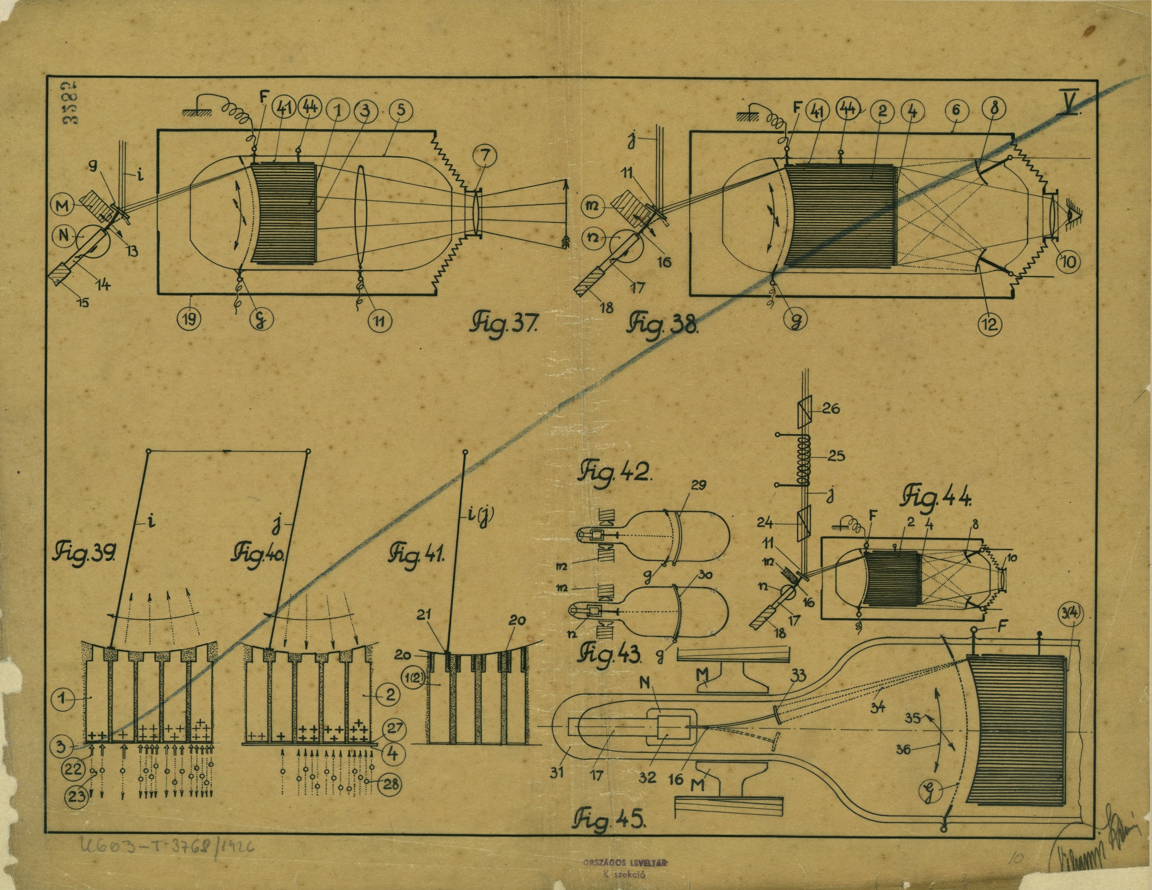
A.III. by scintillation of the radioactive alpha particles through control of the positive alpha beam energy by means of grid effect (see drawing V., Fig. 37-38).
A.IV. by storing the electric energies – controlled through electric impulses – of the individual picture elements in bar bundles: here, the amplified energy of the electric impulse of the picture element flows within the available 1/100,000 s onto a simple bar, which, thus being charged up, makes the intensity of the scintillating or electro- luminescent substance applied onto its end proportionate to the charge. Each of the picture elements–lying on one another and insulated from one another–corresponds to a simple, small metal bar of rectangular cross section with the luminescent layer situated at one of the ground ends of such a bundle (at the cross-sectional front of the bars). The charging of the individual bars is accomplished by a scanning cathode beam at the other end of the bar bundle, in proportion to the electric impulses of the individual picture elements of the transmitting station.
Thus, the stronger electric impulse of a picture element having higher light intensity charges the capacity bar to a voltage value which (due to the connection explained hereunder) induces the layer at the front of the respective bar to a stronger luminescence, while the bar charged by the weaker electric impulse of a darker picture element results in weaker luminescence. Consequentl, the individual bars will be charged up in accordance with the light values of the picture element of the same position at the transmitting station, that is, the voltages controlling the luminescence grades of the bar faces are distributed in accordance with the light values of the transmitted picture. It should be noted that the luminescence can be excited not only by electric, but also by magnetic lines of force (see Ch. Zentralblatt, 1913, p. 209).
The introduction of the electric charge into the bars takes place with extraordinary speed (this will be accomplished by means of the cathode ray), as the available 1/100,000 s time per picture element is abundantly sufficient, while the charged bars maintain the luminescence long enough to be perceived by the eye.
Thus, by storing the otherwise short-lived electric impulses the fault source b will be eliminated simply and efficiently.
B.I. At the transmitting station as well, in place of the sluggish photoelectric cell, the same capacity bar system is employed for elimination of the fault source b, with the modification that, in this case, the faces of the metallic bars are covered with alkali metal (or the bars are made of an alkali metal) and that during the life cycle of the picture (1/10 s) photoelectric charges are accumulated in the individual bars in proportion to the light intensity of the picture detail (picture element) falling on the bar faces. These electrical charges can be then removed during the available 1/100,000 s and transferred, with vacuum tube amplification, to the receiving station (where they can be stored for luminescence in the capacity bars of the receiving “Radioskop” tube). (Bold emphasis added.)
On the attached attached drawings:
I. and V. show two different circuit systems connecting these bar bundle based “Radioskop” tubes with the amplifying vacuum tubes.
II. serves the elucidation of the equations employed in the electrical design of “Radioskop” tubes.
III. Illustrates the principle of the picture control system needing no synchronization adjustment, where the picture controlling currents as well can be transmitted to the receiving station by radio waves, this action being of course controlled from a single location, that is, from the transmitting station.
IV. Represents the complete circuit diagram of these bar bundle based “Radioskop” tubes within the framework of a wireless transmitting station (on the left) and a receiving station (on the right).
B.II. Furthermore, as replacement for the sluggish photocells, the solution according to drawing
VI. can also be used in this system, where, instead of the great number of picture elements,
the picture is transmitted in “picture lines”.
VII. shows a circuit arrangement of the transmitting photocells (e.g. as according to Drawing VI) and of the amplifying vacuum tubes, as well as a system where the light can be transmitted to the receiving station according to wavelengths, that is, in the natural colors of the picture.
The form of execution shown on Drawing I can thus be characterized as a system where the control of the intensity of the capacity bar system charging cathode beam occurs by means of grid control. On the drawing, Fig. 1 is an execution of the transmitting, Fig. 2 of a receiving “Radioskop” tube; Fig. 3 explains the operation of the transmitting, Fig. 4 of the receiving tube; Fig. 6 to 10 are circuit diagrams; Fig. 11 represents a detail drawing of the special hot cathode of these tubes; and Fig. 12 and 13 shows a version of the receiving “Radioskop” tube without the capacity bar bundle.
(…)

Page 30-32 of translation (original pp. 20. § 5 through pp. 22. § 1)
Briefly summarizing, then, the operation is as follows:
In the transmitter and the receiver, the cathode beams, moving synchronously, scan the bars of corresponding positions concurrently, and
At the transmitting “Radioskop”, more electrons will be released from the bar face upon which the incident light is stronger, and proportionally greater charge +Q will remain in the bar as well; based on the equation VA=Q:C, the bar voltage +VA will be greater.
This permits smaller grid current ig, of which the grid - 59 - of the amplifying tube receives smaller grid voltage +er = weaker anode current intensity.
At the receiving “Radioskop”: weaker anode current produces lower grid voltage +eg, this sets smaller cathode beam intensity, thus the negative bar charge is smaller = greater light intensity on the luminescent bar face.
The receiving “Radioskop” tubes without bar bundle shown on Drawing I, Fig. 12- 13, can be produced primarily for smaller pictures (low number of picture elements) employing on the screens - 67 - an electro luminescent substance that, reacting within the picture element time t1, continues phosphorescing for ca.1/200 to 1/10 s. Here, with the grid effect, as outlined, the energy of the luminescence producing cathode beam - k - (see Fig. 12) will be controlled also by the grid - g - according to the current pulse emitted by the transmitting station. Fig. 13 illustrates an executional form of the receiving tube, whereby the luminescent screen
- 67 - is connected to the grid g (with the luminescent screen suitably applied onto an insulating plate, e.g. mica). In both cases, the operation is as follows:
greater current impulse: greater + grid voltage = greater longitudinal field, greater longitudinal cathode beam energy = more intense luminescence.
These receiving tubes, too, will be connected according to Fig. 10 in place of the last amplifying tube (K in place of the cathode, g of the grid, A in place of the anode), calling for circuitry - b - at the transmitter, that is, the negative pin (b) is connected to the grid of the first amplifying tube - 59 -, so that there, too, greater light intensity should correspond to greater current impulse (anode current ia).
Fig. 11 and 14 show two executional forms of the rear hot cathode of the “Radioskop” tube. From the hot cathode according to Fig. 11 (preferably a small, thin strip), only the cathode beam - k - of very small cross section will pass through the diaphragms 50, 51. Namely, in case of the usual, smaller tube units, cathode beams of small, 0.0035 mm2 cross section have to be designed so that during the scanning time t1 (in the case of portraits requiring 100,000/s picture elements 1/100.000 s), given its maximal energy, it charge the bar only to the necessary (126 V) maximum voltage (resulting in total darkness with total suppression of the luminescence).
The hot cathode, emitting convergent cathode beam of greater energy, shown in Fig. 14, will be suitable only for tube units designed for very large number of picture elements. Here, the convergent cathode beam, concentrated onto the end of a bar having the size of a single picture element, originates from the concave surface of the hot spherical shell - 54 -. To render the spherical shell suitable for feeding with small glow current, it is formed of the thin metal band /54/ wound in a spiral, the beginning /55/ and the center /56/ of the spiral being provided with terminals.


Color television. Page 52-54, 56-57, and 64 of translation (original pp. 31-34, and 37)
The picture transmission in color (“Chromo Radioskop”) can be realized through some modification of the above outlined bar bundle system.
To accomplish this, three different luminescent substances are applied to each individual insulated bar, each luminescing in a different primary color. Thus, each bar is divided into three sections, and the charging cathode beam k (Fig. 2, 4) is deflected to the bar section whose frontal luminescence has to be suppressed or decreased, according to the picture element color obtained at the same position of the transmitting station.
[As stated above, the cathode beam k charges the capacity bar to a negative voltage, so that it suppresses the negative electrons of the initial condition which produces the luminescence. In case of the system according to Drawing V, Fig. 38, 40, however, the ionizing beam introducing the positive charges from the grid is to be directed to the bar section where luminescence of the bar face is desired.]
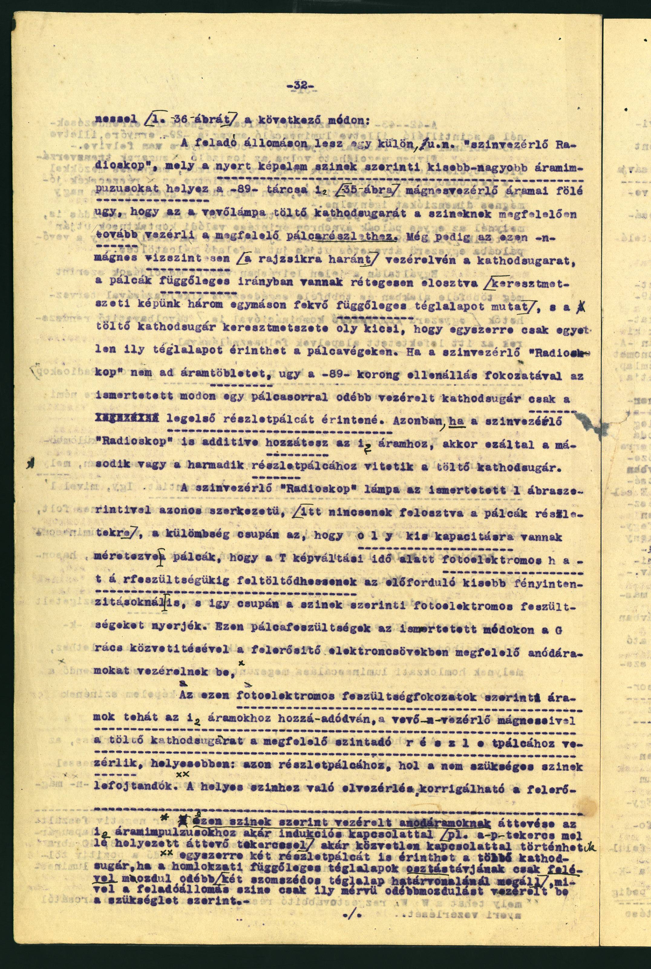
This partial deflection of the cathode beam to the individual bar sections will be accomplished with the picture control electromagnets - m - as well, specifically with one of them, the magnet - n - (see Fig. 36) [which will consequently derive its control from the rotating disc - 89 - through W2, W3 oscillation carrying elements] as follows:
The transmitting station will be provided with a separate, so called “color-control Radioskop”, which, in accordance with the picture element colors obtained, adds smaller/greater current impulses to the magnet control currents i2 of the disc - 89 - (Fig. 35), that in turn directs the charging cathode beam of the receiving tube according to the colors to the corresponding bar section. With the cathode beam deflected horizontally (transversely to the diagram’s plane) by this magnet - n -, the bars are divided vertically (their cross-section shows three vertical rectangles laying next to one another), and the charging cathode beam has a cross-section so small that it impinges on only one rectangle at a time. If the color control “Radioskop” does not supply added current, the cathode beam, shifted by one bar row through the resistor stage of the disc - 89 -, as described above, impinges on only the first bar section. If, however, the color control “Radioskop” adds to the current i2, then, as a result, the charging cathode beam is moved to the second or third bar section.
The color control “Radioskop” tube has an identical structure with that illustrated in Fig. 1 (where, the bars are not divided into sections), the difference being that the bars are designed for such small capacities that they will be charged up to their photoelectric cut-off voltage during the picture repetition time T even at smaller light intensities, and thus receive only the photoelectric voltages corresponding to the colors. In accordance with the methods already described, these bar voltages feed, through the grid G, appropriate anode currents to the amplifying vacuum tubes. [The addition of these color-controlled anode currents to the current pulses i2 can occur either through inductive coupling (e.g. by means of a transmission coil placed next to the coil - p -), or through direct coupling.]
Consequently, these currents corresponding to the photoelectric voltage values, added to the currents i2 with the control magnets - n - of the receiver direct the charging cathode beam to the bar section giving the appropriate color, more precisely, to the bar section where the unneeded colors are to be suppressed.
(…) cont. on page 56 §3-4(orig. page 33 § 5, cont. on page 34)
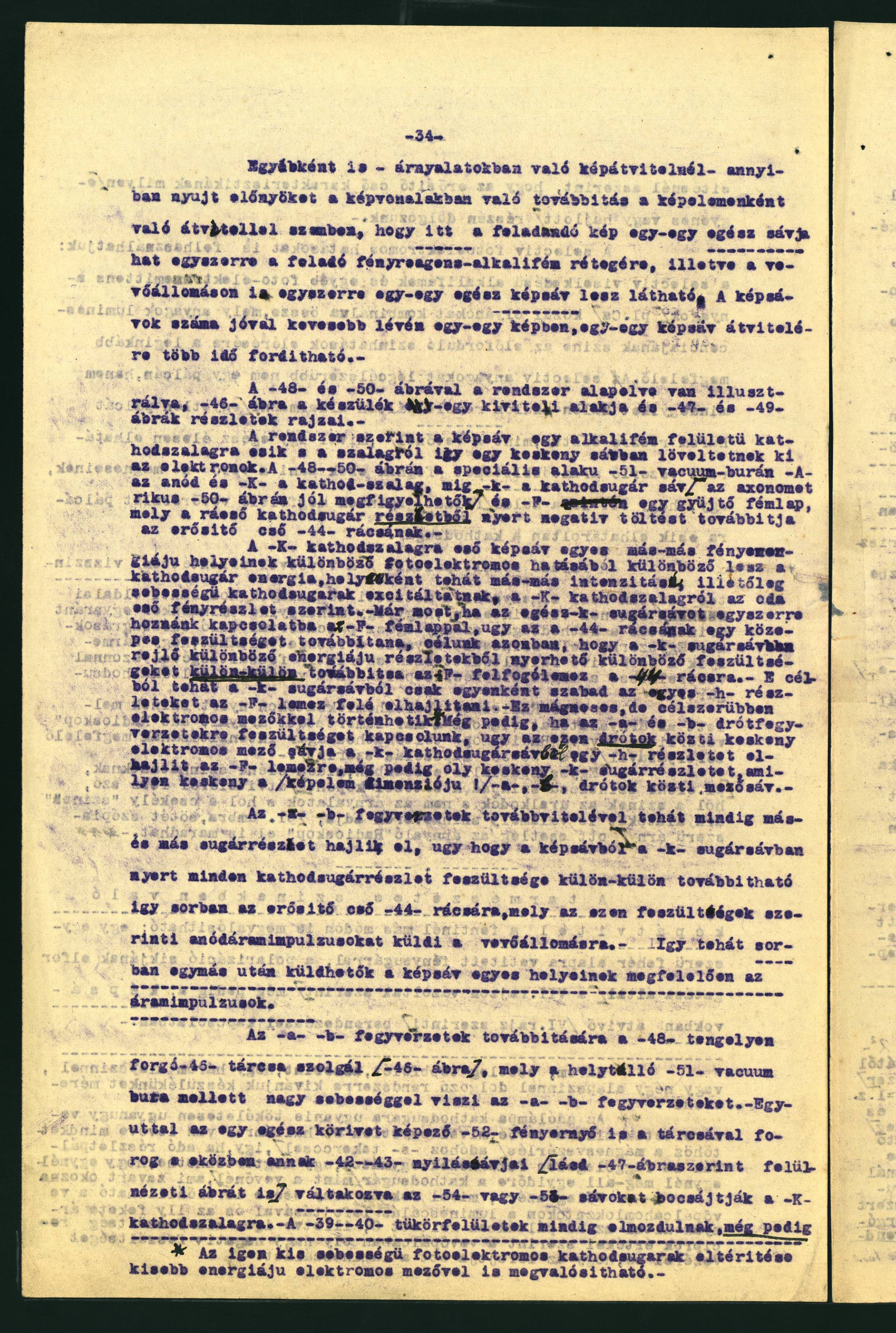
The transmission in natural colors can be accomplished through other methods then described above: by the projection of a light beam onto a simple white foundation through rotation of the plane of polarization (as shown on Drawing VII) in conjunction with the system (according to Drawing VI) featuring transmission by picture lines.
Compared to the picture element based transmission, picture line based transmission – involving transmission of picture gradations – has the advantage that here entire lines of the image to be transmitted influences the light sensitive alkali metal layer of the transmitter simultaneously, respectively entire picture lines will be visible at the receiving station. The number of picture lines being lower in each picture, more time will be available for the transmission of each picture line.
(…) cont. on page 57 (orig. page 34 § 1, 3-4, and related note)
According to the system, the picture line falls onto an alkali metal covered cathode strip, from which the electrons are projected in a narrow line. In Fig. 48 and 50, in the specially shaped vacuum tube - A - is the anode, - K - the cathode strip, while - k - the cathode beam line (in Fig. 50, shown axonometrically), and - F - is a metal collector electrode, which conveys the negative charge derived from the incident cathode beam section impinging upon it to grid - 44 - of the amplifying tube.
Under the influence of the varying photoelectric effect representing individual areas of different light energies in the picture line striking the cathode strip -K - the cathode beam energy will also vary; that is, from place to place cathode beams of varying intensity or velocity are excited according to the light detail arriving from the cathode strip - K -. Should the whole beam strip - k - be brought simultaneously into contact with the metal electrode - F -, then it would relay an average voltage to the grid - 44 -; our goal is, however, that the collector plate - F - relay separately the varying voltages obtainable from the different energy sections inherent in the beam strip - k - to the grid - 44 -. To this end, then, the individual details - h - should be released only one by one from the beam strip - k - to the plate - F -. This can be done with magnetic, but more suitably with electric fields.*
*[The deflection of photoelectric cathode beams of very low velocity can also be accomplished with electric fields of lower energy.]
(…) cont. on page 64 § 4 (orig. page 37, last paragraph)
Although, this latter system does not yield as simple an executional form as the completely
simplified “Radioskop” tube according to Drawings I and V containing all necessary parts and will therefore not be suitable for amateur purposes, nevertheless, it can be used within the framework of other, larger systems, especially for television of natural colors.
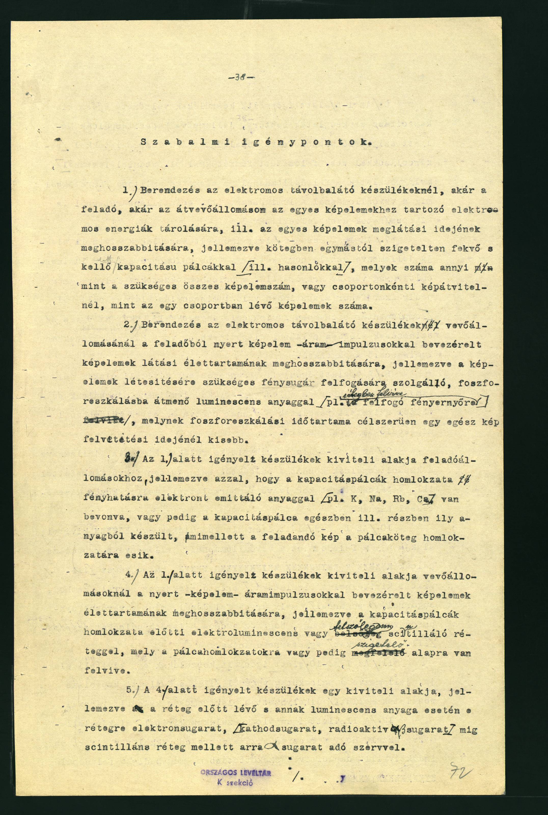


Patent Claims. Page 65-72 of translation (original pp. 38-43)
1. Electronic television system comprising means at both the transmitting and the receiving station for storing the electric energies of individual picture elements, respective for the extension of the projection time of the individual picture elements, characterized by bundled bars (or the like) of appropriate capacity being insulated from one another, the number of bars being equal to the necessary total picture elements or, in the case of group-based picture transmission, to the number of picture elements in one group.
2. Electronic television system comprising means at the receiving station for the extension of the projection time of picture elements controlled by the picture element current impulses derived from the transmitter, characterized by a luminescent substance transiting into phosphorescence (e.g. applied onto the light screen in layers), for the reception of the light beam necessary to produce picture elements, and having a phosphorescence time of preferably shorter duration than the projection time of the entire picture.
3. Device as claimed in claim 1 for transmitting stations, characterized by the fact that the face of the capacity bars is coated with some substance that emits electrons under the influence of light (e.g. K, Na, Rb, Ca), or the capacity bar is made entirely respective partially of said substance, with the picture to be transmitted striking the face of the bar bundle.
4. Device as claimed in claim 1 for receiving stations for the extension of the life cycle of the obtained picture elements controlled by picture element current impulses, characterized by an electro luminescent or, optionally, scintillating layer on the front face of said capacity bars, said layer being applied onto said bar faces or onto an insulating base.
5. Device as claimed in claim 4, characterized by a component in front of the luminescent or scintillating layer, said component generating an electron beam (cathode rays, radioactive beta rays in the case of luminescent substance, or alpha rays, in the case of a scintillating substance) impinging on said layer.
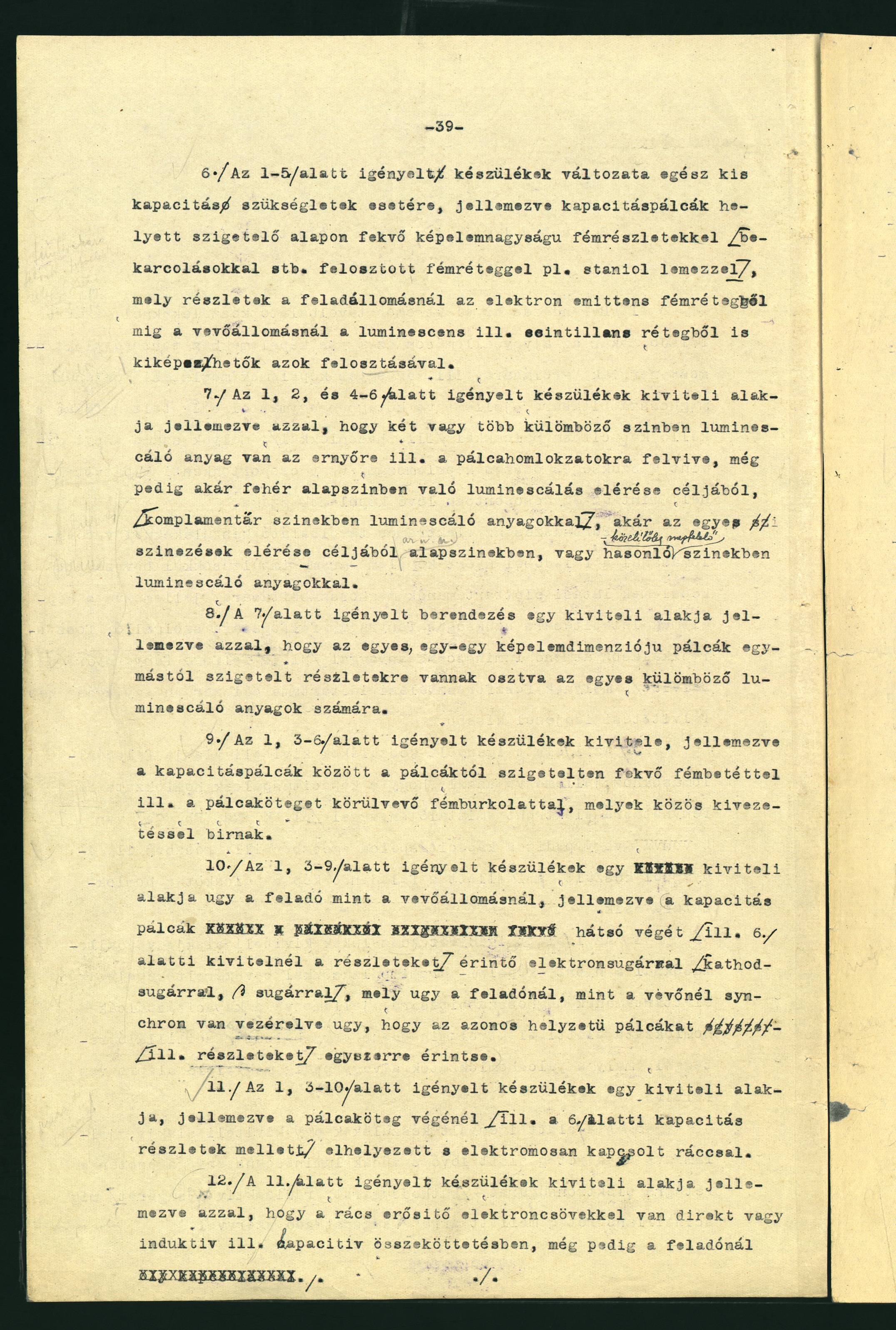
6. An executional form of the device as claimed in claims 1 through 5 for very low capacity needs, characterized, instead of capacity bars, by picture element sized metal particles (metal layer, e.g. aluminum foil, subdivided by scratching or other means) resting on some insulating base, said particles, at the transmitting station, developed from electron emissive metal layer and, at the receiving station, from luminescent or scintillating layer with the subdivision of said layers.
7. An executional from of the device as claimed in claims 1, 2, and 4 through 6, characterized by the fact that a substance luminescing in two or more colors is applied onto the screen respective bar faces for the purpose of achieving luminescence in white (with substances luminescing in complementary colors) or producing various colors with substances luminescing in primary or in roughly equivalent colors.
8. An executional form of the device as claimed in claim 7, characterized by said individual picture element sized bars being divided into sections insulated from one another to accommodate various luminescent substances.
9. An executional form of the device as claimed in claims 1, and 3 through 6, characterized by metal inserts situated between and insulated from the capacity bars, as well as a metal envelope surrounding and insulated from the bar bundle, inserts and envelope having a common electric outward lead.
10. Device as claimed in claims 1, and 3 through 9 for transmitting and receiving stations, characterized by an electron beam (cathode ray, beta ray) exploring the rear face of said capacity bars (respective, in the executional form according to claim 6, the layer segments) controlled synchronously at the transmitting and at the receiving station, so that bars (respective layer segments) of identical position are scanned simultaneously.
11. Device as claimed in claims 1, and 3 through 10, characterized by an electrically connected grid placed at the end of said bar bundle (respective adjacent to the capacity layer particles according to claim 6).
12. Device as claimed in claim 11, characterized by the grid being in direct or inductive, respective capacitive coupling with amplifying vacuum tubes, that is, at the transmitter in such circuit where photoelectric charges – i.e. electric energies controlled by these charges – obtained by the bar bundles (respective layer segments) are transferred from the grid of said device to the grid of said vacuum tubes where they accordingly influence the amplified anode current, while at the receiving station the grid is in such circuit where the anode current – i.e. the electric energies controlled by them – of the last amplifying vacuum tube strike said grid of said receiving television device.
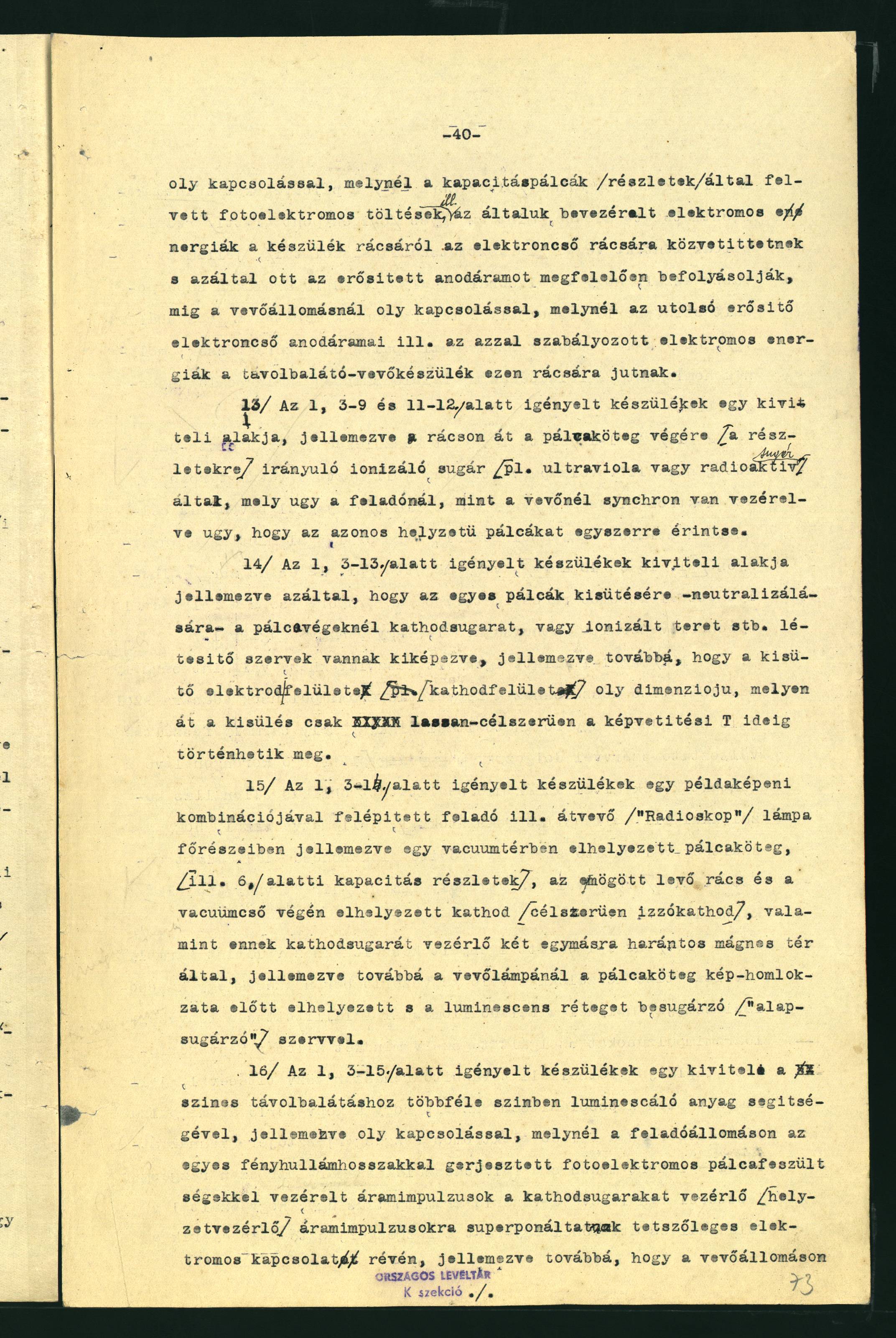
13. Device as claimed in claims 1, 3 through 9, and 11 through 12, in an executional form characterized by an ionizing beam (e.g. ultraviolet or radioactive rays) directed through the grid to the end of the bar bundle (respective layer segments) synchronously at the transmitting and at the receiving station, so that bars of identical position are touched simultaneously.
14. Device as claimed in claims 1, and 3 through 13, characterized by components developed at said bar ends, said components producing cathode beam or ionized field, etc., for the discharge – neutralization – of the individual bars, and further characterized by said discharge electrode surface (cathode surface) having a design through which the discharge can occur slowly, suitably during the picture projection time T.
15. Transmitting respective receiving “Radioskop” tube constructed through a combination of the devices claimed in claims 1, and 3 through 14 with respect to its principal components, characterized by a bar bundle (respective the capacity segments according to claim 6) placed in vacuum, a grid behind it, and a cathode (preferably a hot cathode) placed at the end of the vacuum tube, as well as two magnetic fields transverse to one another controlling the cathode beam of said cathode, and, in the case of the receiving tube, further characterized by a component placed before the face of the bar bundle and irradiating the luminescent layer.
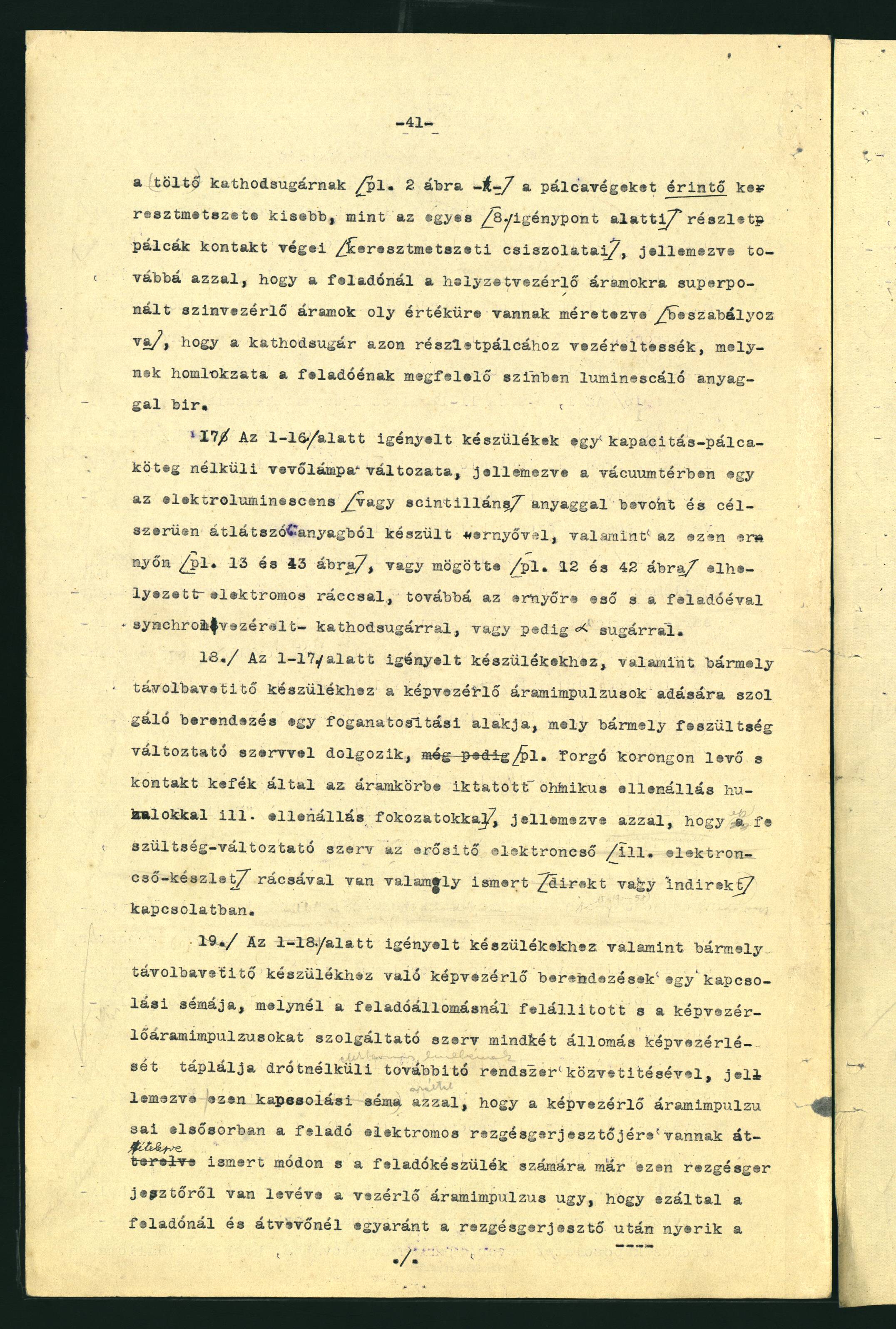
16. An executional form of the device as claimed in claims 1, and 3 through 15 for color television, comprising a substance luminescing in different colors, said color television device characterized by a circuit, where, at the transmitting station, the current impulses controlled by photoelectric bar voltages – generated in turn by the individual light wavelengths – are superimposed through an appropriate electric connection over the current impulses controlling the cathode beams (position control), further characterized by the fact that, at the receiving station, the cross section of the charging cathode beam (e.g. - k - in Fig. 2) exploring the bar ends is smaller than the contact ends of the individual bar segments (as per claim 8), further characterized by the fact that, at the transmitting station, said color control currents superimposed on said position control currents are designed (adjusted) to such value as to direct the cathode beam to the bar section whose face carries the substance luminescing in the color corresponding to that of the transmitter’s.
17. An executional form of the device as claimed in claims 1 through 16 for its receiving tube component without capacity bar bundle, characterized by a screen placed in vacuum space and made preferably of a transparent material coated with an electro luminescent (or scintillating) substance, as well as by an electric grid disposed on (e.g. Fig. 13, 43) or behind (e.g. Fig. 12, 42) said screen, and further characterized by a cathode or alpha beam incident on said screen and synchronized to that of the transmitter.
18. An executional form of the picture control device delivering current impulses, in combination with the television system claimed in claims 1 through 17 and any other television system operating with any voltage control component (e.g. ohmic resistor wires or resistor stages imposed on a rotating disc and rendered circuit by contact brushes), characterized by the fact that said voltage control component is in some known (direct or indirect) contact with the grid of the amplifying vacuum tube (or vacuum tube set).
19. Circuit arrangement of picture control devices in combination with the television system claimed in claims 1 through 18 as well as for any other television device where the component delivering picture control current impulses at the transmitting station performs the picture control at both stations via wireless transmission system, said circuit arrangement characterized by the fact that, in a known manner, its current impulses are coupled primarily to the electric oscillator of the transmitting station and that the control current impulse is derived from said oscillator, so that, as a result, the picture control devices both at the transmitting and at the receiving station obtain their completely simultaneous control current impulses by way of said oscillator.
20. Picture control device as claimed in claims 18, 19, characterized by two discs rotating in forced relation with one another, each disc having disposed on its entire circular arc or on several partial circular arcs resistance wires connected from the center of the circular arc to a slider, one of said brushes being supported by said slider and the other by said resistance wire or wires.
21. An executional form of the device as claimed in claim 20 for discontinuous unidirectional or bidirectional scanning, characterized by one or both discs (suitably the one rotating more slowly) being provided with contact stages – substituting the resistance arc or arcs – between which the resistance stages are applied.
22. Picture control device as claimed in claims 18 through 21 in combination with amplifying vacuum tube system for television (“Radioskop”) transmitting respective receiving tube, in an executional form characterized by an arrangement where the charging cathode beam to be deflected is directed to one corner of or beyond the bar bundle (respective of the section groups, as per the executional form in claim 6), to the effect that said charging cathode beam is deflected to the corner of said bar bundle (or section group) by the minimal anode current associated with the linear section of the amplifying vacuum tube (or tube set).
23. An executional form of the devices claimed in claims 1, 3, and 6 through 9 for transmission by picture line – with or without bar row – with cathode strip, characterized by an electric field strip photoelectrically induced by the picture line and transverse to (respective of transverse efficient component, thus oblique to) said cathode strip, or magnetic field strip oblique to said cathode strip, and further characterized by a device, suitably a rotating disc, for controlling said deflecting field strips, as well as by a collector electrode capturing the electron charge of the cathode beam deflected by said field strip.
24. An executional form of the devices claimed in 1 through 23, characterized by a magnetic field having influence over luminescent substances.
25. Transmitting device in combination with the devices claimed in claims 1 through 24, as well as with any other television or telephotographic device, for the transmission of the light of picture elements according to wavelengths (colors), characterized by a coupling, respective anode voltage, of vacuum tubes effecting the connection between optional transmitting and receiving devices, where the bent, non-proportional section of the tube characteristic will fall above the operating range of the grid voltage, in order that the change of the anode current occur at the desirable ratio between the fixed grid voltage limits.
26. An executional form of the device as claimed in claim 25, characterized by such adjustment of the anode voltage of one or more vacuum tubes mounted anywhere between the alkali metal cell or other electron-emissive cell at the transmitting station and the magnetic coil turning the polarization plane of the light beam at the receiver, that will result in the transmission occurring on the quadratic or near-quadratic section of the tube characteristic.
27. Device claimed in claims 1 through 26, characterized by the fact that the capacity bars (e.g. individual bars of a bar row) are each in connection with known grids located between anode and cathode, said sets of cathode, anode and grid being disposed suitably in a single vacuum envelop.
Excerpt from the original translation, as indicated.
Translated by István Illéssy
Edited by Katalin Tihanyi
© by Katalin Tihanyi Glass
Új hozzászólás